Home made benchtop power suppy
Any electronics tinkerer has a few benchtop power supplies. Growing up as a teenager in in the 1980's in northern Ontario, I didn't have access to, or money to buy a professional quality benchtop power supply. So as usual, I built my own. The one on this page was the last that I'd built, in 1987. I built it with taking it with me to University in mind, so it had to be fairly small.
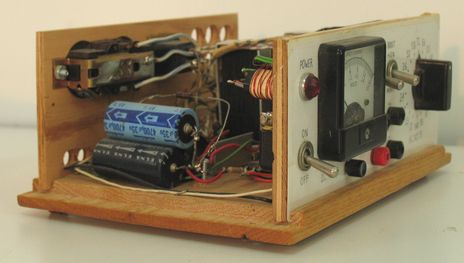
Its an unregulated supply, with no semiconductors other than the bridge rectifier.
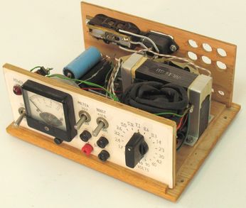
The heart of this power supply is the filament transformer from an old tube tester from 1951. Because tubes in the old transformer-less TVs were all wired in series, Tubes used to come with all kinds of filament voltages, so the tube tester had a many-tapped transformer for selecting the appropriate filament voltage.
|
|
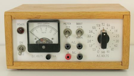
The primary also had two taps on it. There used to be a rheostat between them, so that the voltage of the unit could be tweaked by what the line voltage was (the tube tester itself was also unregulated). I added a switch to allow selecting either of the primary taps to the front panel, doubling the 17 voltage steps to 34. Switching taps changes the output by 12%. I coudln't think of what to label the switch, so I called it 'Boost', because the voltages on the front are for it in the low position. People have often made fun of that label!
The rest was to connect a meter movement, with ranges for 15 and 30 volts DC, and a push button for ampere reading. The meter doesn't need to go past 30 volts, because I wired it up so that past 30 volts, the DC side of the supply cuts out, because the filter capacitors and rectifier I had were only rated for 35 volts. However, AC comes straight out (above the DC terminals) and will go all the way up to 140 volts.
The nice thing about using this supply is turning the knob. It makes a nice sound and has a nice feel switching between voltage taps. And voltages can be adjusted very quickly, if not precisely. But I can usually get close enough for what I need. Very different from tweaking a multi-turned knob and watching a digital LED panel meter to hit the right voltage. Granted, I don't use this one for tricky voltages like charging lithium ion batteries.
The AC output comes in very handy quite often - like when checking out small AC motors, or for powering a degaussing coil. One time, I even brought it in to work to blow out some shorts we had in some prototype printed circuit boards. Without any electronics between the transformer and the terminals, it will put out over 20 amperes for short durations.
I also put two outlets on the back of it, connected to the power cord. I always found myself short of outlets when doing electronics, so being able to plug other things into the back of it often comes in handy.
Also learned an interesting thing about the meter. For the 3-amp current range, I used a steel wire as a shunt resistor, which I tapped at the exact length I needed to get the movement to read full scale at three amperes. Problem with connecting the meter directly to the shunt resistor is that the meter sees the impedance of the shunt resistor, which is practically zero from the meter's point of view. And just the needle swinging causes a lot of back-emf in the moving coil. So on reading current, the meter needle is so overdamped, it seems like it was underwater.
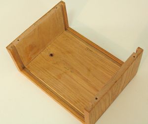
The enclosure, is out of wood of course, because that's what I had handy. Its a nice box made of oak - sturdy and less likely to catch fire that way. The top just slides over the front and back panels, with a groove to hold them in place. That way, with the lid off, the front and back panels are loose, allowing easier access to the insides.
For the front panel, I stuck laminated paper in front of a piece of plywood, with the switches and such mounted through the laminated paper and plywood. This looks really good, but I didn't expect the laminated paper to last all that long. That was in 1987, and it still looks good today, nearly 20 years later. But part of it is that its been in relatively unlit areas most of its life. The front panel lettering was done in pencil, and I had to use the original too, because the photocopiers at my higschool I had access to had a slight bit of distortion to them, so the copies were unusable for this purpose. And the computers I had access to in 1987 were not powerful enough to do that sort of thing with either.
If you use this sort of technique today, I recommend using photo paper on an ink jet printer. I made a new scale for a meter movement that way once. Took a few tries, but it came out looking really good.
Anyways, this power supply is still my favourite benchtop supply, and the one I still use most often today. Its just satisfying to use. It must be the sound and feel of turning that voltage knob!
Back to Matthias Wandel's home page